Soldered NULA CAN ESP32-S3
NULA development board with an ESP32-S3 and an onboard CAN transceiver, so you join a CAN or CAN FD bus through a three-pin plug, no extra module.
Soldered NULA CAN ESP32-S3 is a development board in the NULA format, built around the ESP32-S3-WROOM-1-N8R8 module: a dual-core Xtensa LX7 at up to 240 MHz, 512 KB of SRAM, 8 MB of flash and 8 MB of PSRAM, with 2.4 GHz Wi-Fi 4 and Bluetooth 5 LE. Next to the module sits an NXP TJA1441A high-speed CAN transceiver wired to the ESP32-S3's TWAI controller, so one board is both a CAN node and a wireless device.
CAN_H and CAN_L come out on a three-pin 2.5 mm pluggable terminal block, and the plug is in the package. A 120 Ω termination resistor is connected by default; cut JP3 to remove it. The transceiver covers CAN and CAN FD up to 5 Mbit/s on the physical layer (ISO 11898-2:2016), with TX on GPIO5 and RX on GPIO4. It needs 4.5 to 5.5 V, which it takes from USB or from the VCC pin: on battery power alone the CAN side switches off on undervoltage while the ESP32-S3 keeps running. Power comes in over USB-C with a CH340K USB to UART bridge and automatic reset, through a TP4056M Li-ion charger (400 mA) with a JST battery connector, and a TPS7A26 3.3 V regulator.
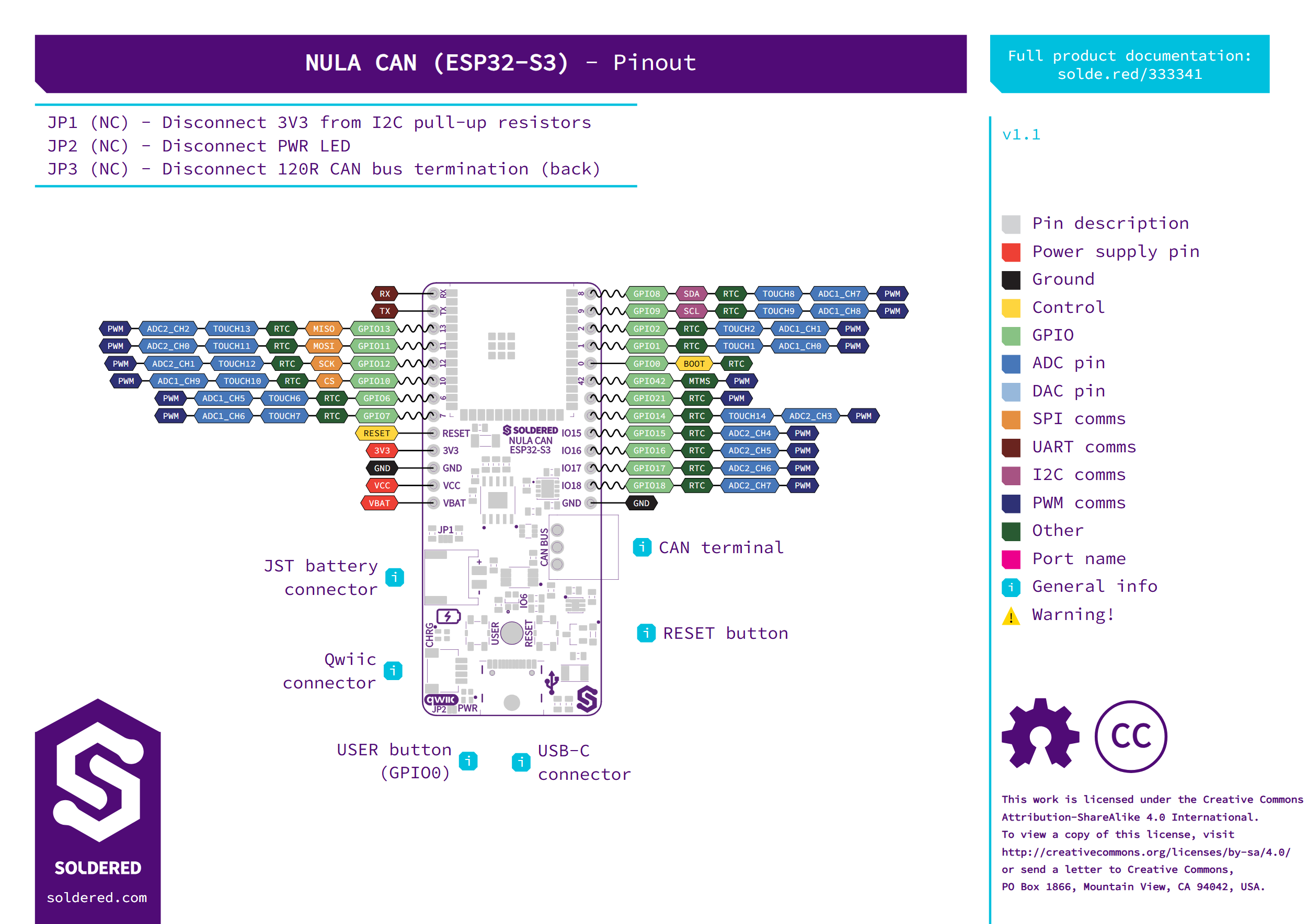
Twenty GPIO pins are broken out on two 13-pin 2.54 mm rows (headers included, unsoldered), so the board sits on a breadboard. The Qwiic connector shares the I2C bus (SDA GPIO8, SCL GPIO9) with 10 kΩ pull-ups you can disconnect at JP1. SPI is on GPIO10 to GPIO13, UART0 on GPIO43 and GPIO44, a WS2812B RGB LED on GPIO6 and the user button on GPIO0. You program it from the Arduino IDE through Espressif's ESP32 core, in MicroPython or in ESP-IDF, where the TWAI driver handles CAN.
- Module: ESP32-S3-WROOM-1-N8R8, dual-core Xtensa LX7 up to 240 MHz, 512 KB SRAM, 8 MB flash, 8 MB PSRAM
- Wireless: 2.4 GHz Wi-Fi 4 (802.11 b/g/n), Bluetooth 5 LE
- CAN transceiver: NXP TJA1441A, ISO 11898-2:2016, CAN and CAN FD up to 5 Mbit/s, TX GPIO5, RX GPIO4
- CAN connector: 3-pin 2.5 mm pluggable terminal block (CAN_H, CAN_L, GND), plug included
- CAN termination: 120 Ω, connected by default, cut JP3 to remove
- CAN transceiver supply: 4.5 to 5.5 V from USB or the VCC pin, off on battery power alone
- USB: USB-C, CH340K USB to UART, automatic reset, 500 mA fuse
- Battery: JST 2-pin connector, TP4056M charger, 400 mA charge current
- Regulator: TPS7A26, 3.3 V, 500 mA
- GPIO: 20 pins on two 13-pin 2.54 mm headers, included unsoldered
- I2C: SDA GPIO8, SCL GPIO9, 10 kΩ pull-ups (JP1), Qwiic connector
- SPI: CS GPIO10, MOSI GPIO11, SCK GPIO12, MISO GPIO13
- UART0: TX GPIO43, RX GPIO44
- Onboard: WS2812B RGB LED on GPIO6, user button on GPIO0, reset button, power LED (JP2)
- Logic level: 3.3 V
- Dimensions: 26 x 63 mm
MCU
| Mcu Part Number | ESP32-S3 |
|---|---|
| Mcu Clock (MHz) | 240 |
| Sram (KB) | 512 |
| Flash (MB) | 8 |
Connectivity
| Wifi | Wifi4 |
|---|---|
| Bluetooth | Ble 5 |
| Wireless Module | ESP32-S3-WROOM-1-N8R8 |
Interface
| Gpio Count | 20 |
|---|---|
| Qwiic Compatible | Yes |
| Breadboard Compatible | Yes |
Power
| Battery Connector | Jst 2Pin |
|---|---|
| Onboard Battery Charger | Yes |
| Supply Voltage | 3V3 5V |
| Logic Level | 3V3 |
Other
| Dev Environments | Arduino IDE, MicroPython, ESP-IDF |
|---|
Connect over USB-C (optional Li-Po battery for portable use).
Install the board definition and library for your language (below).
Upload the first sketch or script and see it work.