Soldered 3-axis Magnetometer BMM350 Breakout
A 3-axis magnetometer breakout with the Bosch BMM350, reading fields to ±2000 µT over I2C through Qwiic or a 2.54 mm header.
The Soldered 3-axis Magnetometer BMM350 Breakout carries the Bosch BMM350 geomagnetic sensor on a 22 x 22 mm board. It measures the magnetic field on three axes, so you can read heading like a compass, detect a nearby magnet or map the field around your project. The sensor also reports its die temperature, which the compensation uses.
The BMM350 covers ±2000 µT on every axis with a resolution of about 0.1 µT. Its zero-field offset stays within ±25 µT before calibration and within ±2 µT after Bosch's eCompass calibration, and it samples at output data rates up to 400 Hz. In normal mode the sensor draws 200 µA at 100 Hz, and suspend mode drops it to 1.8 µA, with a forced mode for single readings in between.
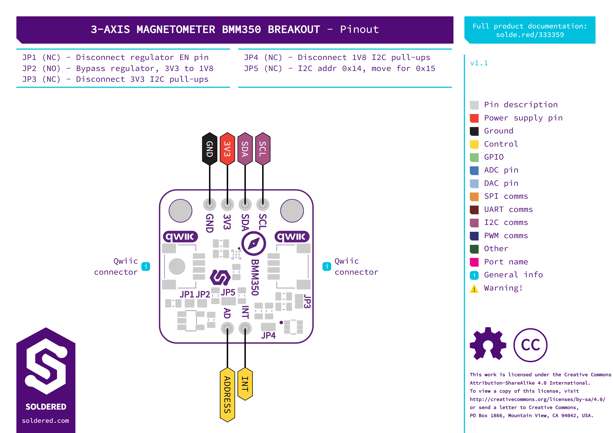
You connect it over two Qwiic connectors or a 4-pin 2.54 mm header (GND, 3V3, SDA, SCL). The header feeds an onboard 1.8 V regulator and an I2C level shifter, so the header side works from 2 V to 5 V. The Qwiic connectors sit on the same supply net, so 5 V on the header reaches them as well. A second 2-pin header exposes INT and ADDRESS straight from the sensor at 1.8 V logic. The default I2C address is 0x14; cut the ADDR jumper and bridge its other side for 0x15. The I2C pull-ups sit on jumpers. Libraries are available for Arduino and MicroPython, plus ESP-IDF and ESPHome components.
- Sensor: Bosch BMM350, 3-axis geomagnetic
- Measurement range: ±2000 µT on all axes
- Resolution: about 0.1 µT
- Zero-field offset: ±25 µT max before calibration, ±2 µT typical after eCompass calibration
- Output data rate: up to 400 Hz in normal mode
- Interface: I2C, address 0x14 (0x15 with the ADDR jumper moved)
- Connectors: 2x Qwiic, 1x 4-pin 2.54 mm header (GND, 3V3, SDA, SCL), 1x 2-pin header (INT, ADDRESS at 1.8 V logic)
- Supply (header): 2 V to 5 V through the onboard 1.8 V regulator and I2C level shifter; Qwiic side 3.3 V
- Sensor current: 200 µA at 100 Hz in normal mode, 1.8 µA in suspend (sensor only)
- Operating temperature: -40 to 85 °C
- Dimensions: 22 x 22 mm, two 3.2 mm mounting holes
Interface
| Interface | I2C, Digital Gpio |
|---|---|
| Qwiic Compatible | Yes |
| I2C Address Default | 0x14 |
| I2C Address Changeable | Yes |
| Breadboard Compatible | Yes |
Measurement
| Measurement Types | Magnetic Field |
|---|---|
| Measurement Range | ±2000 µT on all axes (typical); output data rate up to 400 Hz |
| Measurement Accuracy | Zero-field offset ±25 µT max before calibration, ±2 µT typical after eCompass calibration; sensitivity error ±1 % typical; resolution about 0.1 µT |
Power
| Supply Voltage Min V | 2 |
|---|---|
| Logic Level | 3V3 Only |
| Operating Current (mA) | 3.5 |
| Sleep Current Ua | 200 |
Other
| Ic Part Number | BMM350 |
|---|
Plug into any Soldered Dasduino or microcontroller with an easyC cable — no soldering required.
Add the Soldered library for your language (below).
Open the get-started example and read your first value.