Soldered Smart LED WS2812B Grid 8x8
An 8x8 grid of 64 WS2812B RGB LEDs on an 80 x 80 mm board, driven from one data pin and chainable into larger panels.
The Smart LED WS2812B Grid 8x8 carries 64 individually addressable WS2812B RGB LEDs in an 8 x 8 layout. Each LED has its own driver, so a single data pin from your microcontroller sets the colour of every pixel, and you can show patterns, symbols and animations.
The LEDs sit 10 mm apart on an 80 x 80 mm board and run from 5 V. Every LED has its own 100 nF decoupling capacitor, and a 100 Ω resistor sits in series with DIN. Data enters at the top-left LED and runs in a serpentine: the first row left to right, the next right to left, and so on down the grid.
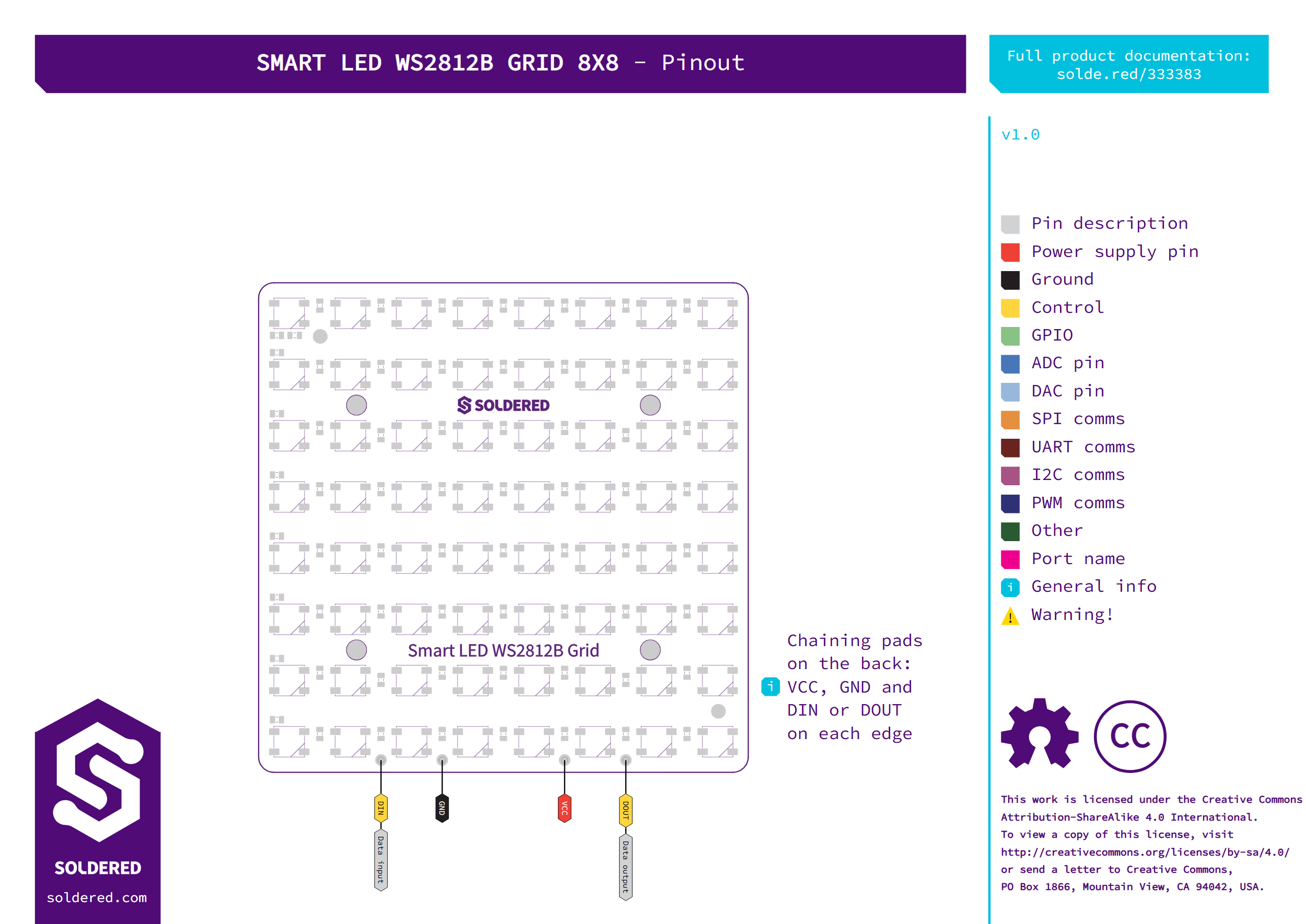
Power and data connect on the DIN, GND, VCC and DOUT header pins. For a bigger panel, connect DOUT of one grid to DIN of the next. Every edge also has VCC, GND and DIN or DOUT solder pads that line up with the neighbouring grid. The Soldered WS2812B Grid Arduino library and the WS2812Grid MicroPython library address pixels by (x, y) across one grid or several. Four 3.2 mm mounting holes let you screw the board down.
- LEDs: 64x WS2812B (5050), 8 x 8, 10 mm pitch
- Interface: single-wire data, DIN in, DOUT out
- Supply: 5 V on VCC
- Data input: 100 Ω series resistor on DIN
- Decoupling: 100 nF per LED
- Header pins: DIN, GND, VCC, DOUT, unsoldered
- Chaining pads: VCC, GND and DIN or DOUT on every edge
- Mounting holes: 4x 3.2 mm
- Dimensions: 80 x 80 mm
Interface
| Interface | Digital Gpio |
|---|---|
| Qwiic Compatible | No |
| Breadboard Compatible | Yes |
Power
| Supply Voltage Min V | 4.5 |
|---|---|
| Supply Voltage Max V | 5.3 |
| Logic Level | 5V Only |
| Operating Current (mA) | 3840 |
Other
| Ic Part Number | WS2812B |
|---|
Wire up to your microcontroller via ['digital_gpio'].
Add the Soldered library for your language (below).
Open the get-started example and read your first value.