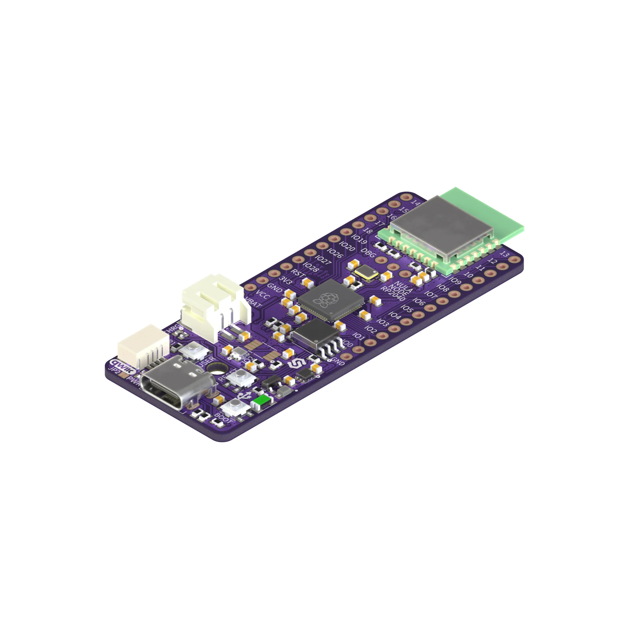
Soldered male pin headers
RP2040 development board with the Raspberry Pi Radio Module 2 for WiFi 4 and Bluetooth 5.2, Qwiic and a Li-Ion charger, with the headers soldered on.
Soldered NULA Node RP2040 is a development board built around Raspberry Pi's dual-core Cortex-M0+ RP2040 at 133 MHz, with 264 KB of SRAM and 16 MB of flash. The Raspberry Pi Radio Module 2 sits on the board, so you get WiFi 4 (802.11 b/g/n, 2.4 GHz) and Bluetooth 5.2 Classic and Low Energy without adding a second board.
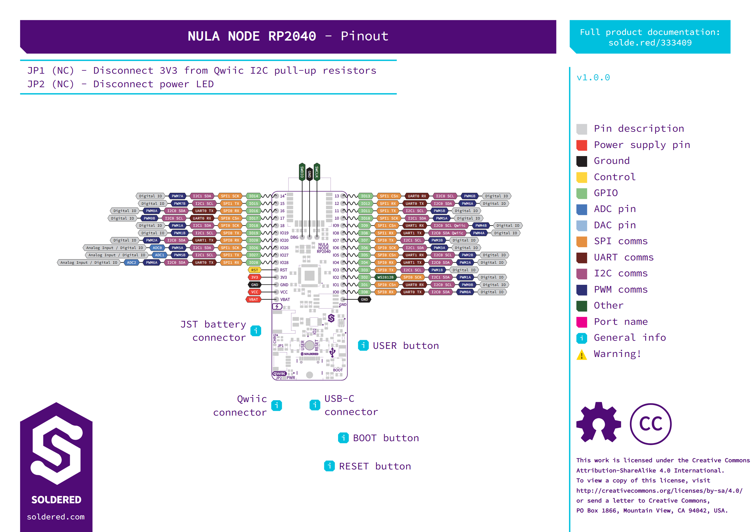
The two 15-pin headers bring out 24 GPIO pins, three of which read analog voltages with the 12-bit ADC. The Qwiic connector carries I2C0 on GPIO8 and GPIO9, with 4.7 kΩ pull-ups you can disconnect at jumper JP1. An addressable WS2812B LED on GPIO2, a USER button on GPIO21, and RESET and BOOT buttons are already on the board, so your first sketch needs no wiring.
Power comes over USB-C, behind a 500 mA fuse, or from a 3.7 V Li-Ion battery on the 2-pin JST connector. The onboard TP4056 charger charges the battery at 400 mA, and the board switches between USB and battery on its own. The VCC header pin takes 3.3 V to 5 V and all logic runs at 3.3 V. The header rows sit 22.86 mm (0.9 in) apart and this version comes with the male headers already soldered, so it drops straight into a breadboard. Program the board in the Arduino IDE through the Raspberry Pi Pico core (board: Soldered Electronics NULA Node), with PlatformIO or with the Pico C/C++ SDK, and use the 3-pin SWD header when you want a hardware debugger.
- MCU: RP2040, dual-core Arm Cortex-M0+ at 133 MHz
- Memory: 264 KB SRAM, 16 MB QSPI flash (W25Q128)
- Wireless: Raspberry Pi Radio Module 2 (Infineon CYW43439), WiFi 4 802.11 b/g/n at 2.4 GHz, Bluetooth 5.2 Classic and Low Energy
- GPIO: 24 on two 15-pin 2.54 mm male headers, soldered, three with 12-bit ADC (GPIO26 to GPIO28)
- Qwiic connector: I2C0 on GPIO8 (SDA) and GPIO9 (SCL), 4.7 kΩ pull-ups to 3.3 V, removable at jumper JP1
- Onboard: WS2812B LED on GPIO2, USER button on GPIO21, RESET and BOOT buttons, power LED (jumper JP2)
- USB-C: power, programming and serial, 500 mA fuse
- Battery: 2-pin JST connector, TP4056 Li-Ion charger at 400 mA, automatic switch between USB and battery
- Supply: VCC header pin 3.3 V to 5 V, 3.3 V regulator TPS7A26 (500 mA)
- Logic level: 3.3 V
- Debug: 3-pin SWD header
- Dimensions: 26 x 65 mm, header rows 22.86 mm (0.9 in) apart
- Environments: Arduino IDE (Raspberry Pi Pico core), PlatformIO, Pico C/C++ SDK
MCU
| Mcu Part Number | RP2040 |
|---|---|
| Mcu Clock (MHz) | 133 |
| Sram (KB) | 264 |
| Flash (MB) | 16 |
Connectivity
| Wifi | Wifi4 |
|---|---|
| Bluetooth | Classic And Ble |
| Wireless Module | Raspberry Pi Radio Module 2 |
Interface
| Gpio Count | 24 |
|---|---|
| Qwiic Compatible | Yes |
| Breadboard Compatible | Yes |
Power
| Battery Connector | Jst 2Pin |
|---|---|
| Onboard Battery Charger | Yes |
| Supply Voltage | 3V3 5V |
| Logic Level | 3V3 |
Other
| Dev Environments | Arduino IDE, PlatformIO, MicroPython, CircuitPython, C/C++ SDK |
|---|
Connect over USB-C (optional Li-Po battery for portable use).
Install the board definition and library for your language (below).
Upload the first sketch or script and see it work.